
Computing
TinyCad
TinyCad is a schematic capture program that can output SPICE compatible netlists. It has library capabilities built in.
A quick summary of tools used to Build and Maintain TinyCAD
1. Microsoft Visual Studio 2003, 2005, or 2008 Standard or Professional (Commercial tool $$$). Initial reports from other programmers are that Microsoft Visual Studio 2010 works without issues,
2. TortoiseSVN or other SVN client (OpenSource tool – free from http://tortoisesvn.net.
3. Doxygen (OpenSource documentation tool – free from http://www.doxygen.org). Doxygen is used to generate special documentation for programmers to help them understand large software projects. TinyCAD was not originally written with Doxygen support, but I am working on adding it.
4. Microsoft’s HTML Help Workshop. This package has tools used to compile the TinyCAD Help files.
5. Nullsoft Scriptable Install System (NSIS) – Use version 2.40 or higher. Older versions may not support the feature set that TinyCAD is using. This very professional installer is Open Source and freely available from http://nsis.sourceforge.net. Of course, it is possible to use any other installer program to construct your own installer for TinyCAD, but other tools are not supported by this developer at this time for lack of resources and time only.
6. Microsoft Windows 7 Software Development Kit. This is a free download from Microsoft.
Note that after installing the Windows SDK, you must run a command from the SDK to update the paths for whichever version of Visual Studio that you are using (otherwise, it will continue to use the older include file path installed by your Visual Studio version). On my particular copy of Windows XP SP3, I found this command using the sequence “Start Menu\Programs\Microsoft Windows SDK v7.1\Visual Studio Registration\Windows SDK Registration Tool”. Select the highest available version in the dropdown version selector box.
Research Links
Business
Stockcharts.com Relative Rotation Graph

JdK RS-Ratio versus JdK RS-Momentum plot
JdK RS-Ratio
The JdK RS-Ratio is a normalized measure of trend in relative strength. So be careful it is therefore not a measure of relative performance as such but it tries to pick up trends in relative performance end measure the strength of such a trend. The JdK RS-Ratio is the input on the horizontal axis on the RRG chart. A universe of stocks or sectors can be ranked based on the values of the JdK RS-Ratio, high values are good, low values are bad. Values over 100 indicate an up-trend in relative strength while values below 100 indicate a down-trend in relative strength.
JdK RS-Momentum
The JdK RS-Momentum line is a normalized measure of momentum/rate-of-change of the RS-Ratio line and is, just like the RS-Ratio line itself, comparable across a universe of instruments. As a momentum / rate-of-change indicator is always leading the underlying (of which the rate-of-change is measured) you will note that the JdK RS-Momentum line will cross the 100-level upward when the RS-Ratio line has formed a trough and is starting to move up. JdK RS-Momentum will cross the 100-level downward when the RS-Ratio line has formed a peak and is starting to move downward.
JdK == Julius de Kempenaer
"RRG charts show you the relative strength and momentum for a group of stocks. Stocks with strong relative strength and momentum appear in the green Leading quadrant. As relative momentum fades, they typically move into the yellow Weakening quadrant. If relative strength then fades, they move into the red Lagging quadrant. Finally, when momentum starts to pick up again, they shift into the blue Improving quadrant."
Research Links
Design Tools
LTSPICE: Dual Modulus 8 9 Current Mode Prescaler Files – Complete Set with IBM 65nM Files Adapted from MOSIS
| LTSPICE: 8/9 Current Mode Prescaler Files – Complete Set with IBM 65nM Files Adapted from MOSIS |
| http://www.amarketplaceofideas.com/wp-content/uploads/2014/12/LTSPICE-Current-Mode-Prescaler-65-nM-IBM.7z |

Electronics
LTSPICE Behavioral Modeling
Research Links
- Analog Behavioral Modeling
- Undocumented LTSPICE
- Google: ltspice digital behavioral models
- HSPICE behavioral modeling
- Nap0's control library
Nap0's Control Library

To use this the library (text file) control.lib must be placed in the directory:
.\LTC\SwCADIII\lib\sub
The symbol files contained in control.zip must be placed in the directory:
.\LTC\SwCADIII\lib\sym\control
(best in the new to be added directory control, so these new blocks do not mix up with the regular components).
Then the symbols are available to be selected amongst the regular components
Business
Free Ebook Yellow Kid Weil and His Grift
The book Yellow Kid Weil will illustrate for you how the politicians and police are in on the grift. It also will teach you the basics of the short and long con game. The storied career of Yellow Kid Weil is an entertaining read and pretty obviously the basis of the movie "The Sting".
Book Links (free DL)
Research Links
Other related books on the same topic of confidence games
- Book: The Big Con PDF, epub
- 48 Laws of Power
- Art of the Con
- Project Gutenberg: The Confidence Man – By Herman Melville ( fiction but likely gleened from anecdotes )
Originally learned of the Yellow Kid from Jean Shepherd / Youtube.
BitCoin
Custom BitCoin Mining Hardware
Appears the days of bitcoins efficiently mined by graphics card are very much over.
Research Links

fzHKZuICbvI9x1NdfKx3
[insert page='bitcoin-cryptocurrency-table-of-contents-toc' display='content']Physics
 [insert page='quantum-mechanics-table-of-contents-toc' display='content']
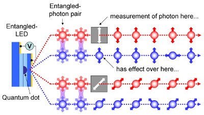
Entangled-Light-Emitting Diode
I really want one of these. But they appear to be vaporware.

Research Links

Conclusions
- Toshiba has a quantum information group
- Likely that a standard LASER's photons are disentangled if they are ever entangled by a "which path" scenario as mentioned below.
Excerpted from Toshiba page:
For some important applications, quantum computers have potentially massive processing power, due to the way data is encoded upon quantum bits (qubits). One of the resources required to operate an optical quantum computer, is entangled light. At Toshiba, our research on entangled light sources has resulted in many important achievements. These include realisation of the first semiconductor source of triggered entangled photons, creation of time-evolving entangled light states, and recently the first electrically driven source of entangled light.
Entangled light possesses the unusual feature that its constituent particles (photons) have inter-related properties, in this case polarisation. Measurement of one photon affects the polarisation of the other, even if they are separated by huge distances. This curious phenomenon was famously declared by Einstein to be “spukhafte Fernwirkung” or “spooky action at a distance”. These properties of entangled light derive from the fact that according to quantum mechanics, the photon pair exist in a superposition state, and the polarisation of the pair is uncertain until measurement of one photon.
We create photon pairs using nanometer-scale regions of semiconductor known as quantum dots. Their small size means quantum dots can capture a maximum of two negative and positive charges (electrons and holes respectively). The electrons and holes recombine to emit a pair of photons.
However, photon pairs emitted by conventional quantum dots are not entangled, as the energies of the emitted photons are polarisation dependent. This means the polarisation of a photon can be determined by measurement of it's energy, providing the dreaded ‘which-path‘ information that is well know to destroy entanglement. We have solved this problem by pioneering a technique to optimise the size and shape of the quantum dot so that the energies of the emitted photons are equal, and entangled light can be emitted. This led to realisation of the first semiconductor source of triggered entangled photon pairs, which we achieved by driving a single quantum dot with a laser.
We have subsequently made many advances in the performance and operation of the device, which include enhanced resolution quantum interferometry, creation of time-evolving entangled states, and improvement of the fidelity, or purity, of the entangled light to 91%. However, entangled light produced previously by us and others requires a laser beam as a power source. For applications such as optical quantum computing that require many entangled photons, the practical advantages of creating entangled light by electrical current are very significant. In collaboration with the University of Cambridge, we now report in the journal Nature, realisation of the first electrically driven source of entangled photons.
Our device is based on a conventional light-emitting-diode (LED) structure, but additionally contains a specially optimised quantum dot. A voltage applied to the LED causes a current to flow, and the quantum dot captures the charge required to emit a pair of photon. In addition, the thickness of the semiconductor material surrounding the quantum dot was optimised to regulate the rate charge is transferred to the dot. Without this feature, entanglement is destroyed by extra charge. We demonstrate that the device works well in both d.c. and a.c. mode, with fidelities up to 82%.
An additional fundamental advantage of the entangled LED is that it has the potential to operate on demand, supplying one entangled pair nearly every cycle. When combined with the practical advantage offered by electrical excitation, the entangled LED will allow simultaneous operation of many entangled light sources on a single chip, opening the path to ultra-powerful semiconductor processors based on quantum computation.
Further Reading