Electronics
Microwave Oven Debugging
Research Links
                                      || +------------------------+
                                      ||( 3.3 VAC, 10 A, typical  |
                        TP  Relay or  || +------------+------+FA F| Magnetron
       _    I       I   __    Triac   ||              |    +-|----|-+
   o--- _---/ --+---/ --  ----/ ----+ || +------||----+    | |_  _| |
                |                    )||( HV Cap      |    |   \/   |
  AC           I \ I=Interlock       )||(           __|__  |   ___  |
 Line           |  TP=Thermal Prot.  )||( 2,000 VAC _\_/_  +----|:--+
   o------------+-------------------+ ||( 0.5 A       | HV      |'--> Micro-
                                      ||( typical     | Diode   |      waves
       (Controller not shown)         || +------------+---------+
                                                     _|_
                                                      -  Chassis ground
Design Tools
LTSPICE: Dual Modulus 8 9 Current Mode Prescaler Files – Complete Set with IBM 65nM Files Adapted from MOSIS
| LTSPICE: 8/9 Current Mode Prescaler Files – Complete Set with IBM 65nM Files Adapted from MOSIS |
| http://www.amarketplaceofideas.com/wp-content/uploads/2014/12/LTSPICE-Current-Mode-Prescaler-65-nM-IBM.7z |

Electronics
Smith Chart Q FootBalls
If you plot a curve of constant ratio of Impedance / Resistance you will see that they plot out football shaped areas on the Smith Chart. See below:
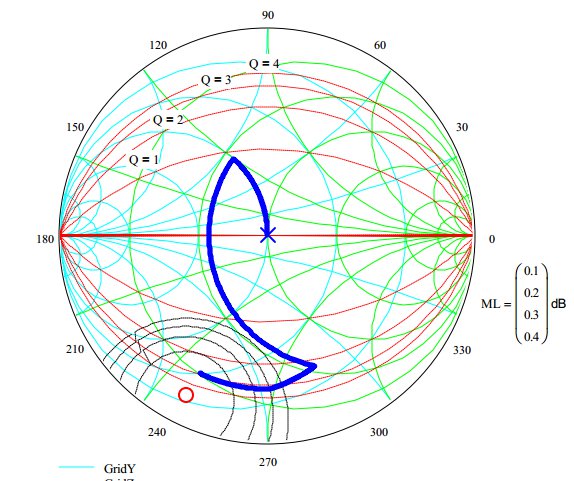
If you are attempting to design the widest band match possible then do not violate the initial footbal in which your load impedance falls.
Microstrip
The HP Half Wave 50 ohm transmission line trick
If your 50 ohm microstrip transmission line varies somewhat in impedance when you are connecting 2 50 Ohm elements together you can use a 1/2 wave length of line in between the blocks if space is available and the design is narrow band. What will happen in a full spin around the Smith chart bringing the load end of the transmission line back to where is started at feed end.
Electronics
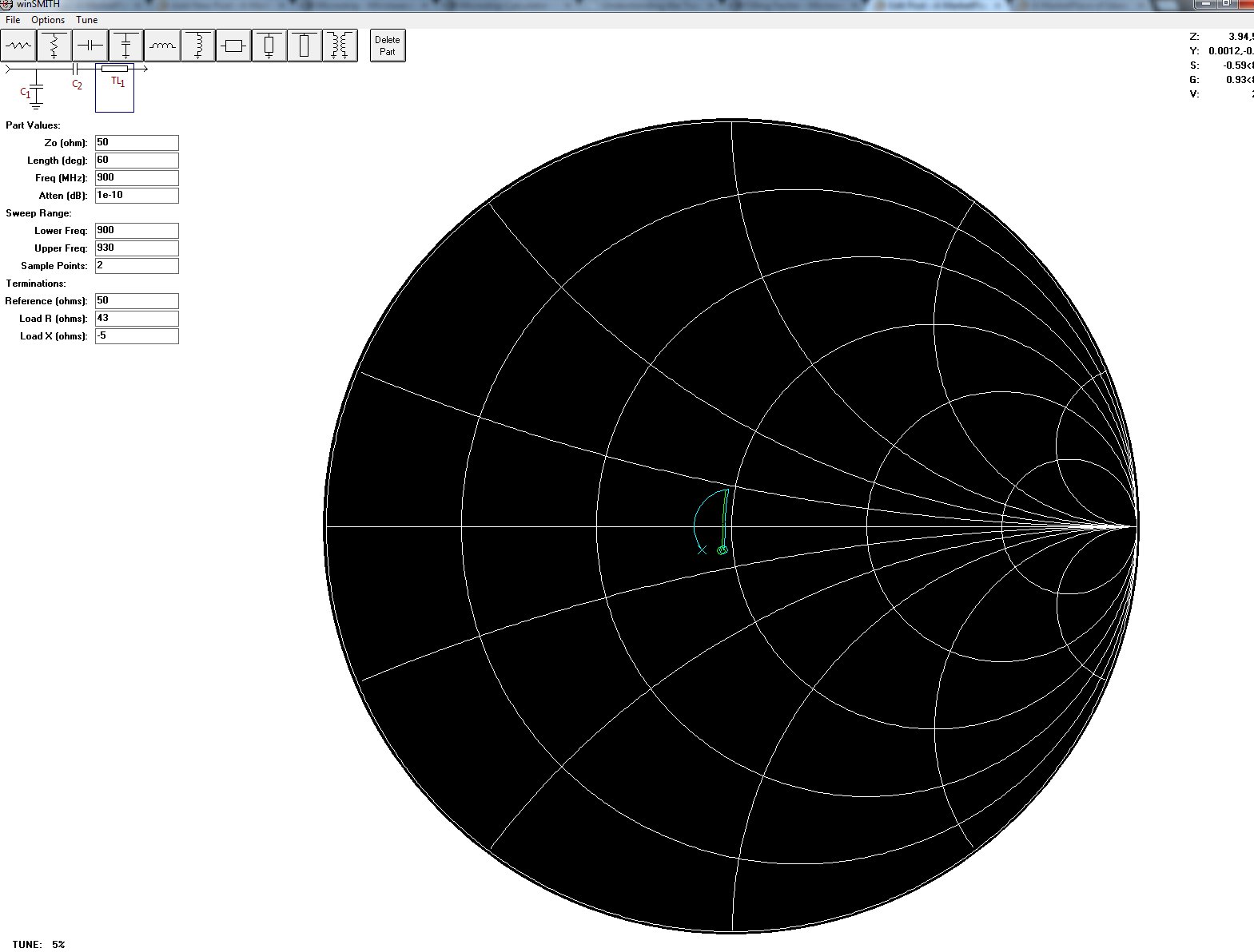
Using WinSmith Program to Design Matching Circuit of 900MHz ISM Band Power Amplifier
WinSmith is a Smith chart match calculating program. The starting point is 8 – j16 ohms @ 915MHz. Both the blue and the green curves start at this point at the lower left of the curves. Click on the image to see a bigger version

What is interesting about the above plot is that the elements work orthogonally. That is to say for any point selected by component of move #2 or move #3 work independently.
The matching circuit is shown below:
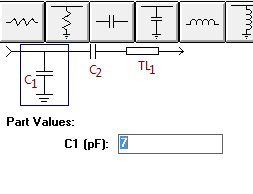
Nominal values
- TL1: 45 degrees of 50 Ohm transmission line @ 900MHz
- C2: 25pF
- C1: 7pF
The left side is 50 Ohms match and the right side is what presents a conjugate match to the FET IC drain circuit. Move #1 on the Smith chart is the 45 degrees of 50 Ohm characteristic impedance transmission line.
Tuning Procedure- theoretical
- The output load of the FET MMIC amplifier will vary somewhat. In spite of this the 45 degrees will transform the load to a region in the charge where the two caps can move the load to the close to the center of the chart.
- C2 has one job only: move the load to a 0.02 conductance circle on the Smith chart. This is the conductance circle that corresponds to 50 Ohms in shunt. Once you know the value of this capacitor you solder in place and leave it.
- C1 is used in shunt to bring the whole thing to the center of the chart. A calculated value can be used for a first try. You may need to cut and try to get absolute optimum on your lab model.
Input Match
The input match is the same topology. It starts much closer to 50 Ohms. The nominal values are
- TL1: 60 degrees of 50 Ohm line at 900MHz
- C2: 22pF
- C1: 0.5pF – This is placeholder in case of surprises. The match looks accomplished without it.
Links
BroadCom Integrated Circuits
Broadcom is not very good at putting out data sheets on their parts. My first line of interest is their point to point radio IC solutions.
Research Links
- Point to Point RF/Microwave Backhaul solutions
- Baseband processing to bits
- BroadCom product line overview PDFp
Backhaul / Point to Point Radio Research Links
- BCM85810 Press release – tells you more than the Broadcom site ( Ouch )