
1k11V6U824
Specifications & Measurements
- Hitch ball size: 1 7/8 or 2 inch ball.
- Maximum hitch height is specified as 25 inches
- Measured natural height of trailer hitch ball receiver: 19 inches ground to bottom ( stopped by a U Haul to get this number. It applies to the hitch seen in the diagram above. Simpler version without auto safety break will be slightly lower.
- Height of the top of the square of my hitch receiver is: 14.5 inches
A rise of about 3 inches would put the hitch at the natural height. Will use the bigger ball.
Research Links
- 6 x 12 foot U Haul Trailer
- UHaul 4 way flat adapter converter
- UHaul 4 Way Adapter Instructions
- Ebay: 7 Pin to 4 way adapter


My best guess is that the converter consists of some connections or resisters + connections at a minimum. Will enter what I find here later.
Auxiliary Links
The trailer hitch design height used worked for a 2100 mile journey. Grateful that is over. Two Arizona trips and a trip to Washington D.C. Ouch. Now if I could only find a used Uhaul trailer. I really like this 2 axle trailer.
Chapter 2
The right hand blinky function would not work on the trailer I purchased after I connected it the second time. Turned out the round to flat adapter must have deformed when I shoved in the adapter.
Debug Sequence
- Shake everything – no help
- connected jumper cable from chassis to trailer – no change
- Drove around the block – contrary to what was suggested the ground does not go through the metal hitch
- checked all the functions – found that only the right blinky / braking display was affected – running lights were unaffected
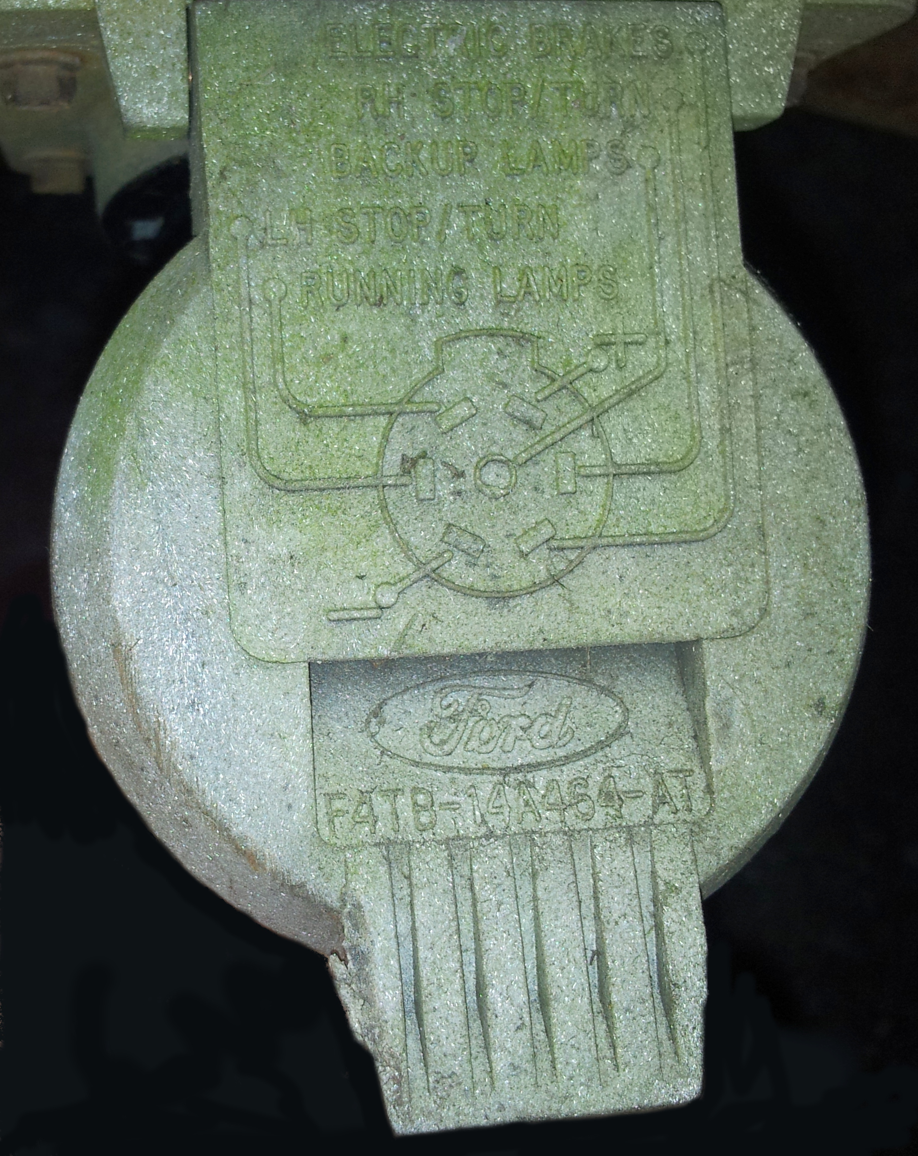
- Used multimeter to see that the right hand Turn / Stop function was the only connection out of the round-to-flat adapter with no signal – Green Wire
- Went and bought replacement fuses – last time I had a problem it was the fuses – Roger helped debug with his buzzy tool – replaced fuse – no change
- Used a cheap battery charger set to 6 volts to show that trailer wiring was not involved – connected to the various pins and saw all wiring good
- Now suspect flat adapter back to fuse box. Used my second adapter – Problem solved. All functions go.
Fuse Box Map


https://www.autogenius.info/ford-e-series-e-150-e150-e-150-1998-2001-fuse-box-diagram/
| Fuse/relay location | Ampere rating [A] | Description |
| 1 | — | Not Used |
| 2 | — | Not Used |
| 3 | — | Not Used |
| 4 | 10 | PCM Keep Alive Memory, Instrument Cluster |
| 5 | 10 | Right Trailer Turn Signal |
| 6 | 10 | Left Trailer Turn Signal |
| 7 | — | Not Used |
| 8 | 60 | I/P Fuses 5, 11, 23, 38, 4, 10, 16, 22, 28 |
| 9 | 30 | PCM Power Relay, Engine Compartment Fuse 4 |
| 10 | 60 | Auxiliary Battery Relay, Engine Compartment Fuses 14, 22 |
| 11 | 30 | IDM Relay (1998 1/2 Vehicles) |
| 12 | 60 | Engine Compartment Fuses 26, 27 |
| 13 | 50 | Blower Motor Relay (Blower Motor) |
| 14 | 30 | Trailer Running Lamps Relay, Trailer Backup Lamps Relay |
| 15 | 40 | Main Light Switch |
| 16 | 50 | RKE Module, Auxiliary Blower Motor Relay |
| 17 | 30 | Fuel Pump Relay, IDM (Diesel) |
| 18 | 60 | I/P Fuses 40, 41 |
| 19 | 60 | 4WABS Module |
| 20 | 20 | Electric Brake Controller |
| 21 | 50 | Modified Vehicle Power |
| 22 | 40 | Trailer Battery Charge Relay (Modified Vehicles Only) |
| 23 | 60 | Ignition Switch |
| 24 | — | Not Used |
| 25 | 20 | NGV Module |
| 26 | 10 | Generator/Voltage Regulator (Diesel Only) |
| 27 | 15 | DRL Module, Horn Relay |
| 28 | — | PCM Diode |
| 29 | — | Not Used |
| A | — | Not Used |
| B | — | Not Used |
| C | — | Trailer Backup Lamps Relay |
| D | — | Trailer Running Lamps Relay |
| E | — | Trailer Battery Charge Relay |
| F | — | IDM Relay |
| G | — | PCM Relay |
| H | — | Blower Motor Relay |
| J | — | Horn Relay |
| K | — | Fuel Pump Relay, IDM Relay (Diesel) |
![]()
Renovation of 125 Year Old House Table of Contents TOC
- — Table of Contents —
- Renovation of 125 Year Old House Table of Contents TOC
- PageListSearch: 1k11V6U824
- —-2016
- How to Build Glass Block Windows
- LED Lighting and Lighting Effects For Original Kitchen Area
- U Haul Trailer Hitch Design
- How to Paint an Interior Wall
- Private: Saw Mills in the Area of East Palestine Ohio
- Brick Laying Robot
- Aerial View of East Palestine Ohio
- Self Cleaning Glass Window Material
- –2017
- The Inevitable Knot in Your Long Extension Cord
- How To Make a Concrete Coffee Table and How to Embed a Metal Design in Concrete
- How to finish as pine floor
- Acceptable Materials for Recycling – an Example Guide – East Palestine
- Drilling Holes in Tight Spaces
- Skid Steer Loaders etc
- The Many Uses of Hogwire
- Houzz Website allows you to solicit advice regarding your homes architecture and repairs
- 1987 Amana Air Conditioner ES122MR
- Easy Concrete, Cement, Cinder Block and Brick Laying using Joint Spacers
- How I do block work Mike Haduck
- Industrial Staircases
- How to build a Farmhouse Table – Uses a Vinegar and Steel Wool Stain
- Hydronic Heating System
- How to Paint Over Oil-Based Paint with Latex
- Large Computer Desk Design
- Garage Door Torsion Spring Calculator
- Industrial Style Interior Design
- How to Hang a door in Existing Jam
- High Quality Lock for Commercial Door
- Installing Garage Door Sealing Strips
- Cutting Cinder Cement Block Using a Diamond Blade and a Circular Saw
- Furnace Fan Squirrel Cage Blower Motor Connection Diagram
- Hampton Bay HBV100 Window Air Conditioner Slider Side Casement
- Guide to Door Lock Measurements
- Masonry Wall with Bullnose Corner Block
- Factory Reconditioned Dewalt DCD940KXR 18V XRP Cordless 1/2 in. Drill Driver Kit
- How to install a steel door
- may 2017
- Computer Desk Ideas
- Fire Testing Thermal Insulation Materials
- Construction Material Notes
- Private: Sources of Cheap Solar Panels
- Greenhouse Plans
- Concrete Tube Hotel
- Introduction to Construction Robotics and the bricklaying robot SAM
- PEX Quick Connect Plastic Tubing and Fitting System for Plumbing replacement
- 300USD DIY Tesla Powerwall – Solar storage 18650 lithium ion home Battery
- —– June 2018
- Disconnecting a lead and oakum seal on a cast iron drain pipe
- Bobs Plumbing Videos – How To Join Galvanized Pipe to P.V.C
- Use AA American Advantage eShopping Portal Directed to Home Depot Website to Maintain AA Airline Miles
- —– may 2018
- Siding Solutions
- —– July 2018
- How to Fit Plasterboard to Ceilings The Easy Way To Hang and Attach Drywall Ceiling Boards
- Basement Entry Construction from Scratch
- Construction Waste Disposal Solutions
- Plaster and Lath Removal and Waste Disposal
- EZ 8 Drum Floor Sander Documentation
- Notes on Antique Toilets
- Replacing a Cellar Wall Drain Line and Plumbing Diagrams
- Repurposed Materials Inc Construction Materials
- —Aug 2018—
- Construction Material Densities
- Basement Foundation Repairs Renovations and Water Management
- Water Management Around a Foundation
- Refinishing and Staining Maple Flooring Wood
- Bathroom Bath Plumbing and Decor Design
- Garage Suites Made Out of Shipping Container
- Old Style 60 Amp Service Fuse Box
- Spider Tie Concrete Forming System
- Stainless Steel Tanks
- Drywall Sheet Rock Plaster Board Hanging Notes
- How to undo a glued PVC fitting
- — oct 2018
- Raised Beach House
- Orbit 62100 Yard Enforcer Motion Activated Sprinkler with Day and Night Detection Modes
- Bathroom Remodeling Structural Support Diagram
- Construction Hoist Design with SpreadSheet
- Reconfigurable Desk
- Private: Business Idea: Chuck Key Specialties
- Zoro.com Abrasives and Sandpaper
- Phone Drawer
- –nov 2018—
- Wiring in Home BackUp Generator Switchover Box
- Clear PVC Pipe
- Exterior Photos of Ohio House – this shows the exterior – page I was looking for
- Secure Aesthetic Front Door
- Mid Century Modern House with Steel and Wood Siding
- —Dec 2018
- Aluminum Downspout Hot Air Solar Collector Construction
- GARN Wood Burning Boiler Heating System
- Pallet Makes a Relatively Attractive Cheap Room Divider
- Private: Matt the Security Guy from Grafton with Side Sales of Surplus Heavy Equipment
- Aircrete Foamcrete Foamed Foam Concrete Lightweight Crushable Concrete Building Material
- —- new entries
- —2019
- PVC Gutter and Downspout Systems
- Titan pump jack scaffold system
- Private: Photos from Mark’s House in Phoenix
- Private: Customized Barbeque Grill
- Cell Phone Booster Amplifier
- Compressor Pressure Regulation Run Control
- Galvanized and Black Pipe Sizes
- Shed Build with Some Good Construction Ideas
- Gas Pipe Sizing and Calculation
- Gingerbread House in Salem Ohio
- Private: LED Lighting for Garage
- How to make a Concrete Counter Top
- Toilet Repair
- Private: Stainless Steel Sources for Fabrication Projects
- Flip Up Bed Storage Space
- IBC Tote Shower
- Architectural Make Over of House
- Dimensions of Plastic Food Grade Barrels
- Old Pine Wood in the Top of the Interior Door Framing from 120 years ago
- How to Shingle Your Shed Jed
- Private: Onan Emerald 1 GenSet 4KW RV Generator
- Pex Fittings with Mounting Flange
- Solar Panels for Beginners: 60 cell vs 72 cell solar panels
- Private: Solar Power Generation – Batteries Charge Controllers and Inverters
- ASCO Transfer Switch Bull 905D Transfer Switch
- REC 310 PE 72 Cell Solar Panel
- Private: Barn Style Door on FB
- Old Gas Furnace DeBugging
- — 2020
- Automobile Grill Desk Counter Bureau
- Well Executed Bunk Beds
- Well Executed Bed Frame Construction
- Beautiful Plumbing
- Shower BathRoom Plumbing Creation
- Interior Plank Wall Designs
- Tongue and Groove Bathroom Wall
- Private: Scaffolding
- Ceiling Beam with White Plank Panel – Hangar Home Private Strip WA68
- E State Road 26, Russiaville, IN 46979 Farm House Built in 1860
- Private: Garage – Big Apartment – Property Details for 1215 Mount Jackson Rd
- Wire Welder, 90 Amp Flux Chicago Electric Welding – Item#68887 36689 Review Harbor Freight Tools
- Private: DC Solar Trailers- Secondary Auction
- Private: Diesel generator Chanfa 195
- Private: N843 Perkins Power Unit – Diesel
- Private: CL: Amazing quality Hardwood pallet boards for all of your home and DIY needs – 1usd (Pittsburgh)
- Private: Furnace Search: 6-19-2020
- Private: Local Lumber Sources
- Where have all the metal scrappers gone?
- Aluminum Roof Top
- Transparent Roofing Materials
- Solar Sheds
- 12 Ways to Get Rid of Groundhogs Permanently
- Refrigerator Get Cold but Freezer Works
- How to fit a metal panelled roof to a wooden shed
- — end of 2020
- —start of 2021
- Build an Insulated Folding Garage Door
- House Accents
- Private: Bradford White IGI-180R-10N Inline Natural Gas Water Heater
- Private: Poulan Pro 330
- Private: Lucas Room Design Elements
- Aircrete Foamcrete Foamed Foam Concrete Lightweight Crushable Concrete Building Material
- —– end new entries—-
- Garage Apartment Architecture – Also Known as Coach House
- House with a Steep Metal Roof – How do you do the roofing job?
- HeadQuarters Architectural Research
- Paint Stripping Notes
- Replacement Red Pine Tongue and Groove Flooring
- Refinishing and Staining Maple Flooring Wood
- How To Install Hardwood Flooring
- Private: Rustys Grade 3 Hickory and Oak Hardwood Flooring
- Old House Water Leak Video
- Ideas for Interior of 120 Year Old House
- Exterior of 120 Year Old House
- Exterior Design for Modern Look of 120 Year Old House – Siding
- Cellar Door Project for 115 Year Old Ohio House
- Ohio Old Wooden House Siding Solutions
- Attic Remodeling Ideas
- Installing a Metal Roof on a Shed as a Practice Exercise
- Private: Construction Tool Inventions
- Joes Pine Floor Refinishing Job
- Basement Foundation Repairs Renovations and Water Management
- Alex Heat Pump Air Conditioner Retrofit for Houses without Duct Work
- Concrete Construction Forms
- Retaining Wall – Large Waste Concrete Blocks 2 foot by 2 foot by 6 foot
- Fire Door Parts and Installation Notes
- Creek Retaining Wall Surge Stone Erosion Prevention
- How to Install a Ductless Mini-Split Air Conditioner
- How To Lay Concrete Blocks
- Retaining Wall – Large Waste Concrete Blocks 2 foot by 2 foot by 6 foot
- —– 2024 —–
- Finished Garage Using Stained Plywood and Metal
0 Comments