
Electronics
Voltage Controlled Oscillator Model HVA121T-6 10.6 to 10.8 GHz
Research Links
Notes
- Tuning Range = 200MHz F0=10.7GHz

Electronics
Electromagnetic Induction: Faraday’s Law Lenz Law and Nonconservative Fields
The lecturer goes into why Faraday's law always holds but Kirchoff's current law only holds with constant flux.
It appears that depending on how you rope your voltage measurement circuit into the same two circuit nodes you get quite different measurement results.
Research Links
Agilent ADS
Agilent ADS: Circuit Envelope Simulation
Research Links
Agilent ADS has several features that set it apart from other design packages. It has nonlinear and "cross frequency" capability. Envelope simulation is where you want to see the envelope of an RF signal.
I suspect ADS will become much easier to use once I understand how various data are held in arrays.
Physics
EM Drive – Massless Propulsion Concept
I have seen something about this before but wrote it off as nuts. Looks like now I need to go through the theory as an exercise.
OverView
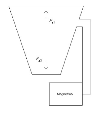
The technique described in this paper uses radiation pressure, at microwave frequencies, in an engine which provides direct conversion from microwave energy to thrust, without the need for propellant. The concept of the microwave engine is illustrated in fig 1. Microwave energy is fed from a magnetron, via a tuned feed to a closed, tapered waveguide, whose overall electrical length gives resonance at the operating frequency of the magnetron. The group velocity of the electromagnetic wave at the end plate of the larger section is higher than the group velocity at the end plate of the smaller section. Thus the radiation pressure at the larger end plate is higher that that at the smaller end plate. The resulting force difference (Fg1 -Fg2) is multiplied by the Q of the resonant assembly.
Research Links
- EM Drive Theory Paper
- Article in the Register: Chinese tested and NASA tested also
- EMDrive website – there is test data
- Warp Field Mechanics 101 – by Sonny White
- NASA's EM Drive webpage
- NASA EM Drive Forum
- EM Drive experiment using microwave oven magnetron -Berca Iulian I am from Romania – Electrical Engineering
Harold G. "Sonny" White Video – later in the video he talks about his EM drive tests.
Electronics
Two Slit Experiment with Quantum Eraser Realized with RF Components

For the optical version see: Home Made Quantum Eraser Experiment Using Laser 2 Slits Polarizer Material
I wanted to think about this experiment in terms of RF components to see if there was anything new I could extract. In RF speak here is what happens.
Description I.T.O. Standard Radio Frequency Speak
With NO Eraser
- Generator / oscillator on a microstrip board generates a vertically polarized wave
- The wave travels down the microstrip to 2 vertically polarized antennas at the edge of the board spaced strategically to give conveniently spaced interference pattern
- Each antenna output next encounters a polarizer oriented at 45 degrees to vertical.
- In RF speak we say that the RF wave is re-radiated from the polarizers. 1/2 of the wave is transmitted and 1/2 is reflected at each polarizer
- The 2 separate streams are now in orthogonal polarizations. Thus I assume they will not be able to interfer with one another at the screen.
- The non-interfering pattern is seen on the screen
- A total power loss of 1/2 is seen,
With Eraser
- Generator / oscillator on a microstrip board generates a vertically polarized wave
- The wave travels down the microstrip to 2 vertically polarized antennas at the edge of the board spaced strategically to give conveniently spaced interference pattern
- Each antenna output next encounters a polarizer oriented at 45 degrees to vertical.
- In RF speak we say that the RF wave is re-radiated from the polarizers. 1/2 of the wave is transmitted and 1/2 is reflected at each polarizer
- The 2 separate streams are now in orthogonal polarizations. Thus I assume they will not be able to interfer with one another at the screen if left as is.
- ERASURE: The 2 separate streams encounter the vertical polarizer. The RF wave is re-radiated from the polarizer with 1/2 going back toward the generator and 1/2 going to the screen. The polarization of stream 1 and 2 are now aligned and thus complete constructive and destructive interference is possible.
- The interfering pattern is seen on the screen.
- A total power loss of 1/4 is seen due to each passing through 2 polarizer stages each oriented at 45 degrees to the stream.
Observation
It is easy to see why there is no interference in the first case. We have arranged for each path to be in orthogonal polarization states. They can not interfere when orthogonal.