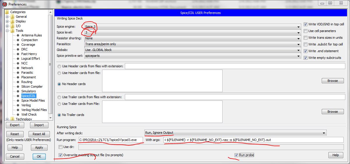
If I use LTspice do I have to modify the SPICE models that I download from MOSIS?
The models I download from CMOSedu.com work great with LTspice but I want to try some other technologies.
Yes, but you will have to change the
-
Change Level = 49 to Level = 8 for the BSIM3 models you download from MOSIS at: http://www.mosis.com/requests/test-data.
-
For the BSIM4 models LTspice uses Level = 54 which is what MOSIS supplies so no change is needed.
​In any case I would download the models, draft a ring oscillator, and compare the simulated oscillation frequency to the measured value reported by MOSIS in these files to verify that the models are working correctly.

|
Archive: The LTSPICE library file made up from MOSIS files and LTSPICE test analysis .asc file: 180nM-NMOS-PMOS-T92Y-MOSIS-LTSPICE-Files-V2.7z
The archive file should work straight out of the box after extraction. Make a directory and extract to it. It has the library file, symbols and an LTSPICE test circuit.
NOTE: When I vary the threshold voltage of the models with this version I do not see any changes in FET analysis. I suspect something is not quite right with this setup. No errors are flagged and everything runs.
|
|
Archive: This LTSPICE archive has model files that are used by using an nmos4 and pmos4 symbol. Thus there is no subcircuit statements used in the library file.
NOTE: With this version when I vary the threshold voltages I see the expected resultant change in the analysis output.
180nm analysis and model files
The archive file should work straight out of the box after extraction. Make a directory and extract to it. It has the library file, symbols and an LTSPICE test circuit.
|
Notes from the process follow. If you want to recreate the process for other MOSIS files they will be helpful.
Research Links
Model Files – No modifications. As is from MOSIS
Notes
-
To bring up the components attributes editor for a part hold control button down and right click on the part. Set the Prefix = X to set the components attributes editor to come up each time you right click on the part.
Auxiliary Links