Electronics
MOSFET Simulation Guide Self Defined MOSFET Model
I have wanted to use the SPICE MOSFET model more closely for while and found this guide: MOSFET Simulation Guide
With it I hope to be able to finally crack the problem of changing the threshold voltage. Up till now when I have gone into the text of the model files for MOSFETs and altered Vth0 I have not seen any material change in the threshold voltage. Obviously I am doing something wrong or do not understand how the SPICE simulator is going about its business.

Research Links
- PDF: MOSFET Simulation Guide – Self Defined MOSFET
- SPICE MOSFET model parameters
- A 180 Nanometer MOSFET Model – Using TSMC Transistor Models from MOSIS in LT Spice
- LTspice Tutorial explains how to import third party models into LTspice
- Creating LTSPICE MOSFET Models
Partial solution to change threshold voltage:
|
Archive: This LTSPICE archive has model files that are used by using an nmos4 and pmos4 symbol. Thus there is no subcircuit statements used in the library file. NOTE: With this version when I vary the threshold voltages I see the expected resultant change in the analysis output. 180nm analysis and model files The archive file should work straight out of the box after extraction. Make a directory and extract to it. It has the library file, symbols and an LTSPICE test circuit. |
Notes
- The unaltered diode connected voltages with 10uAmps agrees with both methodologies.
Design Tools
A 180 Nanometer MOSFET Model – Using TSMC Transistor Models from MOSIS in LT Spice
If I use LTspice do I have to modify the SPICE models that I download from MOSIS?
The models I download from CMOSedu.com work great with LTspice but I want to try some other technologies.
Yes, but you will have to change the
- Change Level = 49 to Level = 8 for the BSIM3 models you download from MOSIS at: http://www.mosis.com/requests/test-data.
- For the BSIM4 models LTspice uses Level = 54 which is what MOSIS supplies so no change is needed.
​In any case I would download the models, draft a ring oscillator, and compare the simulated oscillation frequency to the measured value reported by MOSIS in these files to verify that the models are working correctly.

|
Archive: The LTSPICE library file made up from MOSIS files and LTSPICE test analysis .asc file: 180nM-NMOS-PMOS-T92Y-MOSIS-LTSPICE-Files-V2.7z The archive file should work straight out of the box after extraction. Make a directory and extract to it. It has the library file, symbols and an LTSPICE test circuit. NOTE: When I vary the threshold voltage of the models with this version I do not see any changes in FET analysis. I suspect something is not quite right with this setup. No errors are flagged and everything runs. |
|
Archive: This LTSPICE archive has model files that are used by using an nmos4 and pmos4 symbol. Thus there is no subcircuit statements used in the library file. NOTE: With this version when I vary the threshold voltages I see the expected resultant change in the analysis output. 180nm analysis and model files The archive file should work straight out of the box after extraction. Make a directory and extract to it. It has the library file, symbols and an LTSPICE test circuit. |
Notes from the process follow. If you want to recreate the process for other MOSIS files they will be helpful.
Research Links
- Using TSMC Transistor Models from MOSIS in LT Spice – shows the few steps involved in setting up the MOSIS files for use with LTSPICE. It is minimal procedure
- Adding New Models to LTSPICE – This page will show you how to make your own part so you do not have to share the MOSFET symbol. Helps when you do not want to have to remember as much. Faster starts when you come back after not working with for a while
- MOSIS Test Data Page
- Tips for Converting Level 49 HSPICE models to Level 7 PSpice models
- BSIM3 Parameter Table
- Model Parameter Binning
Model Files – No modifications. As is from MOSIS
- MOSIS T92Y 180nm SPICE file – the file I want to use
- MOSIS N99Y 0.25 uM SPICE file – the file used in the example of how to adapt MOSIS files. See first link above.
- tsmc180nmcmos.lib – uses tsmc-018/t92y_mm_non_epi_thk_mtl_params.txt
Notes
- To bring up the components attributes editor for a part hold control button down and right click on the part. Set the Prefix = X to set the components attributes editor to come up each time you right click on the part.
Auxiliary Links
Computing
Open Source Software: Timing Editor
I needed to draw a timing diagram for a mixed signal class I took. I found
The problem I was solving is shown below in the image. It's rather tedious to figure out. You have to remember that once a gate capacitance is charged up it ideally holds that charge until it is connected to again by either Vdd or Ground.
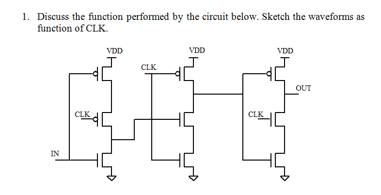

The gate turns out to be a falling edge triggered flip flop. You can see it in the wikipedia:flip flop article that includes this diagram which was found after I did the timing diagram.

Electronics
Current Mode Logic and Prescaler Project Notes
|
Project Report: Please note I ran out of time so the organization and writing of this report is lacking. It does cover the basics of designing an 8/9 dual modulus prescaler. |
If you improve upon this report please come back to this post and put a link to your improved version in the comments.
Research Links: CML Prescaler
- An Analysis of MOS Current Mode Logic for Low Power and High Performance Digital Logic
- A LOW POWER PRESCALER, PHASE FREQUENCY DETECTOR, AND CHARGE PUMP FOR A 12 GHZ FREQUENCY SYNTHESIZER – Evan Lee Eschenko – has a basic cml gate
- A Dynamic-Logic Frequency Divider for 5-GHz WLAN Frequency Synthesizer
- Design of MOS Current-Mode Logic Standard Cells Technology: NSC 0.18 µm CMOS9
- High-Speed CMOS Dual-Modulus Prescalers for Frequency Synthesis by Ranganathan Desikachari
- NEW CML LATCH STRUCTURE FOR HIGH SPEED PRESCALER DESIGN
- A 3.8-mW 2.5-GHz Dual-Modulus Prescaler in a 0.8 µm Silicon Bipolar Production Technology
- ECEN620: Network Theory Broadband Circuit Design
- High Speed Communication Circuits and Systems – Lecture 14 – High Speed Frequency Dividers
- Design of a 5.8 GHz Multi-Modulus Prescaler – Good discussion of how multi modulus prescaler works – block level state machine
- Frequency Dividers – Jri Lee
- Generalized Multi Modulus Dividers using 2/3 cells
- A 1.8V, 3GHz 16/17 Dual Modulus Prescaler in 0.35µm CMOS Technology – has merged Nand D Flip Flop, D Flip Flop and Merged 3-input AND & NAND D-FF topologies for the architecture realization
- A New Dual-Modulus Divider Circuit Technique – I like the way he draws the CML logic block diagrams
Research Links: CML to CMOS converter circuit
This lecture talks about how you need a level shifter for transistor inputs lower on the input ladder of CML logic.
Support Links
- lecture7 – Current mode logic – MUX, XOR, Latch
- lecture8 – Current mode logic – Latch design
- IIT Video Lectures on VLSI Broadband Communication Circuits by Prof. Nagendra Krishnapura
- 74HC193 presettable up / down counter LTSPICE files
- Binary Counter
- Avant HSPICE – Performing Behavoiral Modeling – The entire book
- A Digital Frequency Synthesizer Using Phase Locked Loop Technique – Gursharan Reehal
- Pulse swallowing frequency divider with low power and compact structure Has TSPC registers
- High Speed Communication Circuits and Systems – Lecture 14 – High Speed Frequency Dividers
Additional Links
Communication
FireChat – FireBase – Smart Phone Mesh Network Application
Research Links
- FireChat
- OpenGarden – but FireChat is proprietary!
- FireBase – FireChat
- FireChat documentation
This application was used in Iraq and Honk Kong when the rulers shut down the internet.